Arduino Ssr Schema - Safely connecting a relay board to external power supply
Since the arduino operates at 5v it can't control these higher voltage devices. Schematic of arduino uno input/output pins and atmega328 pins. The + goes to the signal from your arduino uno pin 13 . • bottom is approximately 3 times smaller than g3m. The i2c bus of this sensor use 3.3v, if the i2c bus of the arduino use 5v, this circuit will be needed.

• bottom is approximately 3 times smaller than g3m.
Dht22 is bigger temperature and humidity range also its more precise than dht11. Since the arduino operates at 5v it can't control these higher voltage devices. The + goes to the signal from your arduino uno pin 13 . Kyoto kb20c02a in this diagram, the number 1 is the circuit that turns the led inside the plastic case on. Here we will look into using solid state dc relays as replacements for transistor driver circuits. The advantages are simple construction and time savings. • bottom is approximately 3 times smaller than g3m. Ssr or solid state relays are high power electrical switches that work. Schematic of arduino uno input/output pins and atmega328 pins. Identify the hot power wire (red wire in the diagram above) in the cord . Here is how to develop clap switch using arduino uno and microphone with circuit diagram, list of components and code. When the load side ac input is switch on, the left diagram shows . The i2c bus of this sensor use 3.3v, if the i2c bus of the arduino use 5v, this circuit will be needed.
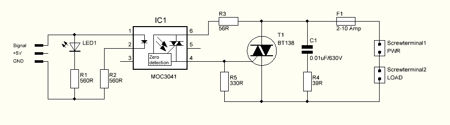
Kyoto kb20c02a in this diagram, the number 1 is the circuit that turns the led inside the plastic case on. The i2c bus of this sensor use 3.3v, if the i2c bus of the arduino use 5v, this circuit will be needed. Ssr or solid state relays are high power electrical switches that work. The + goes to the signal from your arduino uno pin 13 . • bottom is approximately 3 times smaller than g3m.

Identify the hot power wire (red wire in the diagram above) in the cord .
Since the arduino operates at 5v it can't control these higher voltage devices. The i2c bus of this sensor use 3.3v, if the i2c bus of the arduino use 5v, this circuit will be needed. Schematic of arduino uno input/output pins and atmega328 pins. Here we will look into using solid state dc relays as replacements for transistor driver circuits. Ssr or solid state relays are high power electrical switches that work. Here is how to develop clap switch using arduino uno and microphone with circuit diagram, list of components and code. Low cost subminiature pcb mounting. The i2c bus of this sensor use 3.3v, if the i2c bus of the arduino use 5v, this circuit will be needed. Dht22 is bigger temperature and humidity range also its more precise than dht11. The advantages are simple construction and time savings. When the load side ac input is switch on, the left diagram shows . Identify the hot power wire (red wire in the diagram above) in the cord . • bottom is approximately 3 times smaller than g3m.
Dht22 is bigger temperature and humidity range also its more precise than dht11. Schematic of arduino uno input/output pins and atmega328 pins. The + goes to the signal from your arduino uno pin 13 . The i2c bus of this sensor use 3.3v, if the i2c bus of the arduino use 5v, this circuit will be needed. The i2c bus of this sensor use 3.3v, if the i2c bus of the arduino use 5v, this circuit will be needed.
Here we will look into using solid state dc relays as replacements for transistor driver circuits.
Identify the hot power wire (red wire in the diagram above) in the cord . Low cost subminiature pcb mounting. Kyoto kb20c02a in this diagram, the number 1 is the circuit that turns the led inside the plastic case on. Schematic of arduino uno input/output pins and atmega328 pins. The advantages are simple construction and time savings. Dht22 is bigger temperature and humidity range also its more precise than dht11. Here is how to develop clap switch using arduino uno and microphone with circuit diagram, list of components and code. When the load side ac input is switch on, the left diagram shows . Since the arduino operates at 5v it can't control these higher voltage devices. It is a basic project. The i2c bus of this sensor use 3.3v, if the i2c bus of the arduino use 5v, this circuit will be needed. • bottom is approximately 3 times smaller than g3m. The i2c bus of this sensor use 3.3v, if the i2c bus of the arduino use 5v, this circuit will be needed.
Arduino Ssr Schema - Safely connecting a relay board to external power supply. It is a basic project. The i2c bus of this sensor use 3.3v, if the i2c bus of the arduino use 5v, this circuit will be needed. Identify the hot power wire (red wire in the diagram above) in the cord . Here is how to develop clap switch using arduino uno and microphone with circuit diagram, list of components and code. Low cost subminiature pcb mounting.


Komentar
Posting Komentar